Project · October 2026 · Solo
Smart desk fan
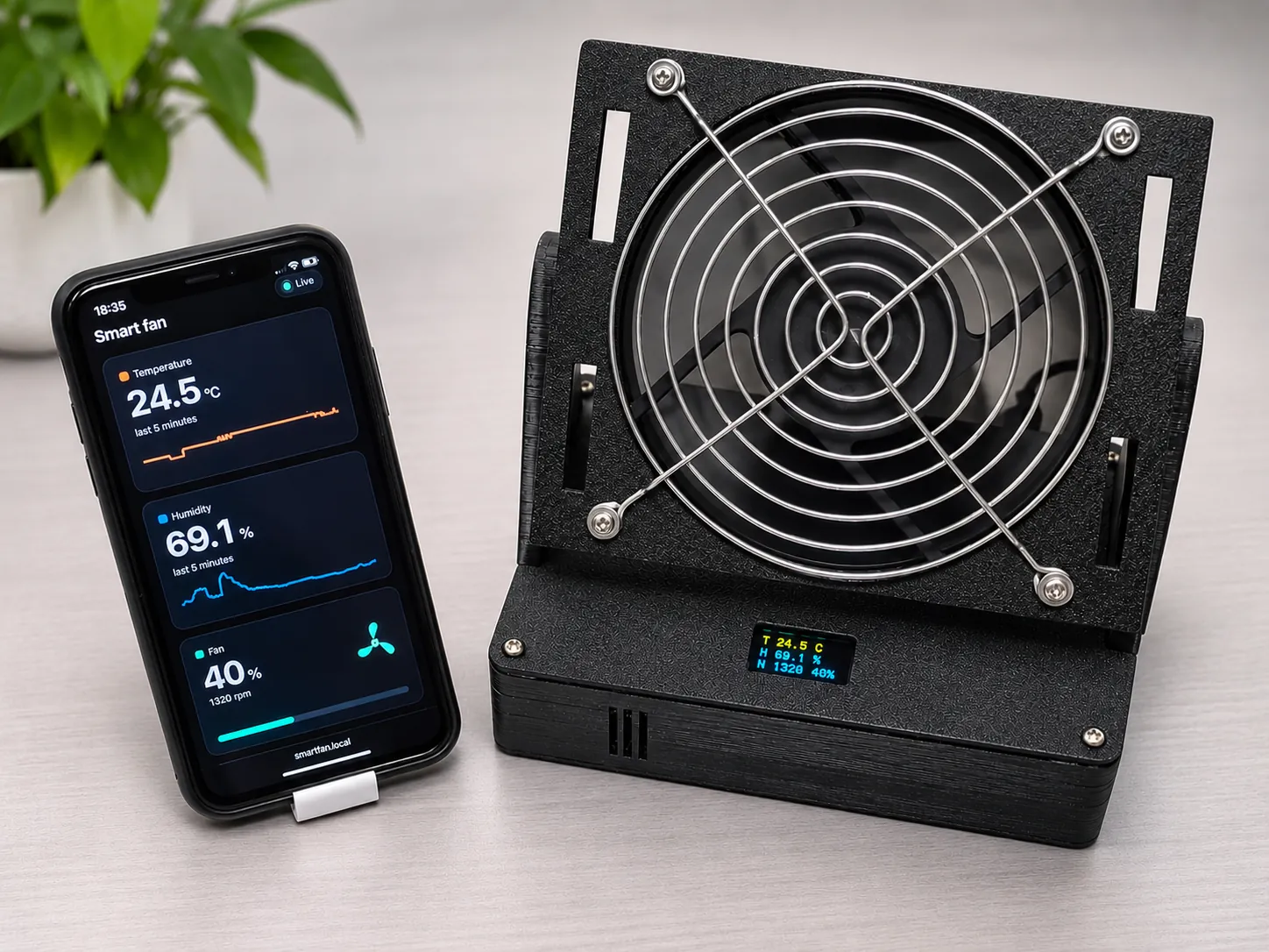
A 12 V PC fan that sets its own speed from the room temperature. An STM32F411 runs the control on FreeRTOS. An ESP32 next to it provides a web dashboard, OTA updates and MQTT. Hardware, firmware, tests and CI were all designed and built in this project and tested on the real hardware.
What it does
A 12 V PC fan on a desk that adjusts its own speed to the room temperature. The STM32 reads an AHT20 sensor, decides a target speed, drives the fan with PWM and measures the real speed from the tachometer. An ESP32 next to it handles the network side: dashboard, OTA updates and MQTT.
Firmware on FreeRTOS
Six tasks with deliberate priorities. Data moves between them only through FreeRTOS objects: mailbox queues (xQueueOverwrite / xQueuePeek) for the latest sensor and speed values, a command queue for mode changes, a stream buffer filled from the UART interrupt, and task notifications from interrupts. Periodic tasks run on fixed periods with vTaskDelayUntil.
A real torn read. Writing a value and its timestamp is two stores, and a higher-priority task can run between them and read a new value with an old timestamp. volatile gives visibility, not atomicity. A one-slot mailbox hands over the value and its timestamp as one copy.
/* before: two stores, a reader can run in between */
g_temp     = reading;
g_temp_ts  = xTaskGetTickCount();

/* after: one sample, copied in and out of a one-slot queue */
xQueueOverwrite(tempBox, &sample);   /* writer */
xQueuePeek(tempBox, &sample, 0);     /* readers */
Simplified for this page.
Control: a comfort curve, after a PID that was the wrong model
The first version used PID. A desk fan does not cool the room, so the temperature does not respond to the fan and there is no loop to close. The fan only changes how warm it feels. The control was replaced with a comfort curve that maps temperature to speed, with three additions:
- Hysteresis so the speed does not hunt when the temperature sits on a step.
- Slew-rate limit so speed changes are gradual and quiet.
- Kick-start so the fan reliably starts from standstill at low duty.
Fan drive and speed measurement
TIM1 generates the PWM at 25 kHz, driving the fan through a transistor stage. The real fan speed comes from the tachometer, measured with TIM2 input capture and filtered twice: in hardware with the timer's input filter and in software. The tach input needed both, see the debug log below.
The AHT20 and the SSD1306 OLED share I2C. When the sensor is unplugged, the firmware recovers the bus instead of hanging, and when readings go stale it falls back to a safe fixed speed.
STM32 to ESP32 link
UART with DMA in both directions: receive-to-idle on the RX side and a circular buffer. The protocol is a small text protocol with an NMEA-style XOR checksum. Both ends validate strictly and drop anything that does not parse completely.
The control and protocol code has no dependency on HAL or FreeRTOS, so it compiles and runs on a PC for testing.
ESP32: dashboard, OTA and MQTT
- Web dashboard served from flash: live values, 5-minute graphs, mode buttons, a speed slider and offline detection.
- REST endpoints:
GET /status.jsonandPOST /mode. - Password-protected OTA updates and automatic Wi-Fi reconnect.
- MQTT with PubSubClient to a Mosquitto broker with authentication: a retained state topic, online/offline status through Last Will, and a command topic with strict input validation.
- Secrets stay out of git.
C++, Arduino framework, PlatformIO.
Tests and CI
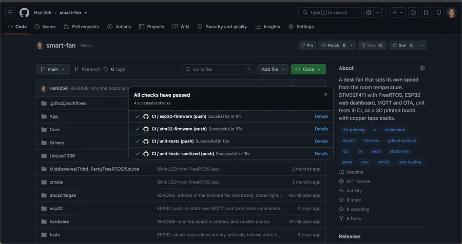
47 unit tests with Unity and CTest cover the control logic, both ends of the protocol and the ESP32 parser. They run with gcc and clang, and again under AddressSanitizer and UndefinedBehaviorSanitizer.
The tests found two real bugs:
- Fan speed oscillated at low manual speeds.
- The checksum parser accepted a space as a hex digit.
GitHub Actions runs four jobs on every push:
Hardware
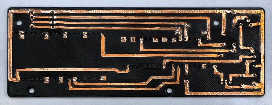
The circuit board is single-sided and 3D printed in PLA, with copper tape laid on raised tracks. It is a fast and cheap alternative to ordering or etching a PCB, and it needs no jumper wires. The second revision fixed a flipped module footprint found on the first. The enclosure is 3D printed too. The repository has a BOM and a board build guide with the pin map, polarity, wiring and first power-up.
Debug log
Problems found and fixed on the bench:
- TACHAn open tachometer path.
- TACHNoise on the tach input. The speed measurement is now filtered in hardware and in software.
- UARTGarbage on the UART link, traced to a loose ground.
- WIFIWi-Fi association failures.
- MQTTBroker authentication issues.